As you know, VAZ 2108 cars with a low panel are not equipped with such a useful device as a tachometer. Owners of “nines” with a high panel also often have complaints about the operation of the standard tachometer. When a device fails, it is quite expensive to buy new switches; they often cost from 1,500 rubles. Inexpensive copies may be unreliable. Therefore, in this article we will look at installing and connecting an electronic tachometer to our car. Traditionally, we will do the installation ourselves.
This device costs around 800 rubles. It works flawlessly, and there have been no complaints about its performance from people using it yet. In addition to its main function - measuring and displaying on the display the number of revolutions of the engine crankshaft per unit of time (usually revolutions per minute), the electronic tachometer has additional and useful built-in functions. For example, individual units can signal when the engine speed exceeds a given limit, measure the voltage of the on-board network, have a built-in clock, stopwatch, alarm clock, etc. This device can go into standby mode when the engine is turned off to reduce its power consumption, but even in operating mode it will not noticeably affect the load on the car battery; the power consumed by the electronic tachometer does not exceed 1.5 W.
Installation of the device is quite simple; you need to connect only 3 wires to the car's electrical wiring, 2 of which are the power supply for the device. Power can be supplied from the cigarette lighter; the negative wire can be secured to ground in a convenient place. We connect the third wire to terminal “K” of the ignition coil, or to the switch.
You can install our electronic tachometer on a VAZ 2108 using double-sided tape, using it to secure the device to the steering column casing.
For a VAZ 2108 with a low panel, you can build such an electronic tachometer into the instrument cluster instead of the “STOP” indicator lamp display, and place the control buttons on the inside upper part of the visor of the instrument cluster. Looks very cool.
This installation is considered using the example of the TX-517 device; there are also many analogues; you can choose a device to your liking.
The most common malfunction of this type of device is burnout of indicator segments in devices with a low-quality display.
I would also like to note that installing a digital tachometer is rational for carburetor VAZ 2108 cars. On cars with an injection engine, in my opinion, a more rational solution would be to install an on-board computer. It has much wider functionality, as it reads many parameters from the engine control unit and can display them on the display. Connecting it will also not be difficult; you can read about it here. True, it costs noticeably more. In general, decide for yourself!
Many car enthusiasts know very well why and for what purpose engineers came up with a tachometer in cars. Some people don’t look at it at all, and some cars don’t even have it. Is there an electronic tachometer for these cars?
Operating principle
The tachometer records the number of pulses supplied from the sensors. The pauses between pulses and the order in which they arrive are also taken into account. The counting process can be carried out using both forward and reverse directions. Indicators are often translated into a certain value. This value can be any indicator. Most of these devices can be reset. As for the accuracy of the readings, it is quite conditional. The best quality electronic tachometer has an accuracy of about 100 rpm.
Operating principle and functionality
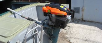
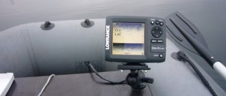
The operating principle of electronic devices for outboard motors (outboard motors) is based on the induction method. The tachometer reads signals in the engine's electrical system. They come from Magdino coils. The magneto-dynamo pair plays the role of a generator. The number of pulses per revolution of the crankshaft corresponds to the number of magdino lighting coils, or pole pieces. There can be 4, 6, 8 and 12. Reading pulses is not related to the number of cylinders and strokes, which allows the device to be used for both a two-stroke engine and a 4-stroke engine with a number of cylinders from 2 to 6.
To set the poles, there is a switch on the back of the device that corresponds to the number of poles.
Often, boat owners install car tachometers that read pulses from the ignition system from the SZ wires through the insulating material. In a 4-stroke engine with 4 cylinders, to generate a spark from the SZ, 2 pulses are generated per 1 revolution.
Assembling an electronic tachometer with your own hands
Why buy when you can assemble everything yourself? It's not that expensive and quite interesting. There are several device options for assembly. These devices are assembled on the basis of contact or non-contact sensors. In non-contact optical systems, laser or infrared rays are used to register pulses. The time of one revolution is calculated. Let's see how to build your own optical recording device using an Arduino-type microcontroller.
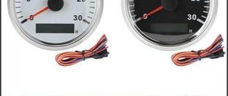
Most popular models
Powerboat manufacturers do not manufacture or supply engine measuring devices. They are produced by separate companies - partner firms. Thus, Teleflex Marine produces tachometers with the Mercury, Osculati and Teleflex logos. On Japanese and Chinese models you can see the Yamaha and Suzuki trademarks.
List of models and manufacturers of boat tachometers:
When choosing devices, experts recommend taking into account not only compatibility with outboard motors, but also the technical parameters of the device.
Source
Electronic tachometer circuit on Arduino
To assemble the device, you will naturally need an Arduino microcontroller. If it is not there, then any other controller with similar characteristics will do, but then you will need to additionally assemble the programmer. Also for this circuit you need resistors 33 kOhm, 270 Ohm, 10 kOhm in the form of a potentiometer. You can also purchase a blue LED, an infrared LED and a photodiode. Next, find the DSV display and the shift register chip labeled 74NS595. It uses an optical sensor and the principle of reflecting rays. With this system, you don't have to worry about how thick the rotor should be, and the number of rotor blades won't change the performance. The sensor will be able to accurately read the revolutions.
Further according to the scheme
Resistors and their values may vary slightly. It depends on the diodes. A variable resistor makes it possible to change the sensitivity level of the resulting sensor. So, the “ground” is connected to a 33 kOhm resistor and a variable resistor, which, in turn, is connected to a wire that needs to be installed in front of the potentiometer. The negative of the LED is connected through the remaining resistor to ground, and the positive goes to the Arduino. So, we got three outputs - ground, plus and signal wire. This circuit uses an 8-bit shift register and display. It is advisable to consider recesses for the indicator in the case. Now a 270 Ohm resistor is soldered to the LED and then installed in pin 12 of the microcontroller. Now the electronic tachometer is ready. You can start programming and calibrating it. The program for Arduino can be found on automotive resources.
Post navigation
Seal the contacts with a good waterproof sealant. Bow tank boat electric motors, which are installed in the bow of boats and boats with a rigid hull. The device is located near the river. To connect the motor connector to the battery, in the simplest case, you need flat auto connectors: 1 male and 1 female.
The only difficulty that may arise is the aesthetic installation of the connecting harness next to the gas reverse machine.
Each has its own fuse and is connected with a separate cable. By poorly securing the clamps, you run the risk of finding out: what engine displacement looks like, what a sudden deterioration in controllability is, the threat of an accident, pah-pah, of course. Some models include a safety cable. To set the time until service, press and hold for 4 seconds.
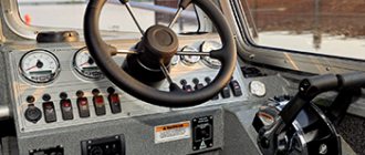
Constant load. A complete shift of the steering wheel is usually carried out in two and a half turns. The price of an analog tachometer is RUR.
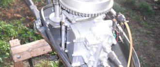
Operating principle and installation
The other end of the steering cable is connected to the engine. The cable should not come into contact with moving or hot parts of the motor. What diameter should I use?
In the same way, you can search for the generator coil wires and connect the regulator on motors of other brands and models. Hence the versatility of tachometers designed for outboard motors - as a rule, a special selector switch is installed on the reverse side, turning which sets the mode corresponding to the number of magdino poles. The device can operate in two modes. How to choose a tachometer The market for accessories and devices for boats and motors is diverse. Choosing a boat steering cable The first thing when choosing a cable is to correctly calculate its length.
According to the instructions, the second end of the wire is inserted into the groove on the back of the device. Boat remote control device A mechanical steering system has an advantage over a hydraulic one in its simplicity of design and relatively low price, but is inferior in the precision of motor control. Almost all models presented on the Russian market have standard fastening units. Moreover, for the most common four-stroke four-cylinder engine, one revolution of the crankshaft corresponds to two openings of the circuit, causing the formation of a spark at the spark plugs. Installing a gearbox on a Suzuki 90 ATL outboard motor
Another homemade tachometer
In order to measure the number of revolutions, as we already know, counting the pulses of the breaker or the voltage from the spark plugs is used. The frequency of these pulses is linearly related to the motor speed. You can also try to organize an inductive coupling with such a circuit, which will be demonstrated in this device. The basis for this option is a single-vibrator labeled LM 555.
Gasoline devices also differ in the number of cylinders
So, everything is bought. Now decide where you will install the electronics. Many are placed on the dashboard, others are mounted near the ignition switch. However, it is best if the electronic tachometer is installed in a place where it will not spoil the appearance of the panel.
To secure it, a car enthusiast’s best friend – double-sided tape – will help. This universal remedy saves in a variety of situations.
Installation and configuration of the device
First you need to purchase the device itself and the connecting cable. Most often it is advised to buy a branded cable, which is already equipped with everything. Let's analyze the installation with a Yamaha tachometer , which has a fuse for power surges.
Take measurements on the boat first so you know what length of harness you will need. One part of it is connected to the connectors on the remote control machine or to the ignition switch. Despite the fact that the dashboard is nearby, there is a risk of missing.
The main stage is installing the device into a panel, usually a non-removable one. The best option is when the panel is located at a certain angle. Do not place the device on horizontal places. Draw the outline of the future hole and mark its center, and then work with a drill.
Connecting the device yourself
Not everyone understands electronics, but it is still desirable to be able to connect a measuring device. This will not cause any difficulties, because there are only three wires. The first thing to do is take the wire from the tachometer into the engine compartment. The easiest way to do this is through the hole in the speedometer cable. Next you will need a piece of wire. It should be about one meter long, thin and tough. At one end, use electrical tape to secure the wire from the device. Try to work carefully. Carefully insert the other end of the wire into the holes in the cable and push. Connecting an electronic tachometer can be done as follows. The positive wire is connected to the ignition coil (pin B). Connect the signal wire to contact K of the same coil. Connect the minus to ground. Work as carefully as possible, the wires are very thin and very unreliable.
A tachometer is a device for measuring the rotation speed of engines, shafts, and other mechanisms. The tachometer has been used in transportation technology for more than a hundred years. As a rule, it is installed on the dashboard. The device indicates the rotation speed of the internal combustion engine during operation. In modern cars equipped with electronic engine control systems, it is not always installed. However, the tachometer readings allow you to select the most suitable driving mode. In some cases, this allows you to save fuel or, conversely, switch to a more aggressive driving style. Therefore, experienced car enthusiasts and professional drivers often install dashboards with tachometers on their own.
Let's look at how to independently connect a tachometer.
How to choose
The existing market for tachometers for outboard motors is quite diverse and is represented by both models of well-known brands and products of unknown companies. In addition, you can find fakes on the market.
Therefore, first of all, you need to choose a reliable seller (ask where friends and acquaintances bought tachometers, look at reviews on online forums, etc.).
When choosing a tachometer, you need to pay attention to such factors and design features as:
- Tachometer functionality. There are instruments that only show the speed of a boat engine.
But there are also tachometers, which, in addition, have the ability to display the following engine parameters:
- number of engine hours;
- temperature;
- oil pressure and much more;
When choosing a tachometer, you need to proceed from the fact that many functions are only possible with special sensors, the installation and installation of which is quite complicated. Most owners of motor boats believe that the optimal choice is a tachometer with a function for calculating the number of engine hours.
This function is important when running in a new engine, as well as for determining the remaining engine life. To do this, you need to choose a device that displays the number of engine hours both during one trip and their total number since the start of operation.
- Compliance of the technical characteristics of the tachometer with the parameters of the outboard motor. It is important to know here that there are tachometers that have built-in operating mode switches depending on whether the engine is used, two-stroke or four-stroke; do not have operating mode switches and are designed to work with one type of engine from different manufacturers; designed to work with engines of a specific manufacturer. For example, DF series motors are only available with 12-pole generators.
- Easy to install, install and configure.
- The tightness of the device. In most tachometers, sealing is ensured structurally, so the power source can only be replaced by disassembling the housing. However, there are tachometers that provide the ability to replace batteries without disassembling the case. This undoubtedly convenient feature can lead to water getting inside the tachometer housing, which will lead to its failure.
- Compactness of the device.
- Tachometer cost. It is of no small importance for a certain category of buyers, inducing them to choose a Chinese manufacturer. However, even among Chinese-made tachometers there are reliable models made with high quality. In addition, well-known manufacturers often offer universal, combined devices, some of the functions of which may not be needed at all, but will significantly increase the price of the tachometer.
In addition, when choosing a digital tachometer, you must ensure that you have sufficient:
- What fuel supply systems exist in a diesel internal combustion engine?
- speed (frequency) of updating information on the display;
- brightness and clarity of the display of numbers on the display, especially in sunny weather.
The principle of operation of the tachometer
Currently, tachometers are distinguished:
- Mechanical. A mechanical tachometer receives information about engine speed using a rotating cable mechanically connected to the engine crankshaft. Nowadays such devices are practically no longer used in cars;
- Electromechanical. The operating principle of electromechanical tachometers is based on the conversion of electrical impulses from sensors installed on the engine or from other electronic devices. These signals are converted into magnetic pulses that deflect the needle of the measuring device like a pointer voltmeter;
- Digital. Digital tachometers are used as part of modern computerized panels and are controlled by software and hardware. Self-installation of this type of tachometer is almost impossible.
Instructions for tachometers for outboard motors
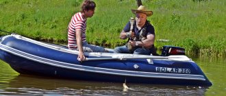
Developers and manufacturers of outboard motors, as a rule, do not set themselves the task of equipping the latter with any measuring instruments. This is due to the fact that boat engines are incomparable in complexity to engines for a car or motorcycle. They are much simpler and therefore do not require any measurements of operating conditions during operation.
However, the operation of outboard motors has shown that in many cases it is extremely necessary to know the real engine speed, but, unfortunately, it is impossible to determine them without a special measuring device. To determine the speed of the outboard motor in real time, a device called a “tachometer” is used.
Its use allows:
Ways to turn on the tachometer
Information about the rotational speed of an internal combustion engine can be read from:
- generator;
- crankshaft speed sensor;
- camshaft speed sensor;
- ignition coil control pulse.
The generators of some cars (for example, Volkswagen T4) have an additional alternating voltage output, the frequency of which depends on the engine speed. In these cars, the signal to the tachometer is supplied from this point.
It is irrational to change the generator just to install a tachometer.
Tachometer connection diagram
The crankshaft and camshaft speed sensors operate on the electromagnetic principle. Earlier cars had sensors using the Hall effect. In any case, the electrical pulse generated by these devices has an amplitude of no more than 5V, and their internal resistance is at least 200 Ohms. In order to connect the tachometer to these sensors, an additional amplifier is required. It is most effective to use a more powerful impulse coming to the ignition coil.
Ignition system for gasoline engines
Control of engine ignition processes can be organized by several methods:
- Distributor with one ignition coil;
- Distributorless with a dual (triple, quadruple depending on the number of cylinders divided by 2) ignition coil;
- Individual (for each spark plug).
In all cases, the coil receives a powerful pulse with an amplitude of 12V from a breaker (for cars before the 90s), a transistor switch, or directly from the engine control unit. It is from this point that the signal to the tachometer should be taken.
Technical solution
Before connecting the tachometer, it is necessary to draw up an electrical connection diagram in order to mentally determine the starting and ending switching points and trace the conductor. Any ignition coil has a terminal (terminal) +15 (ignition on), to which battery voltage is supplied when the key is turned to the first (for some cars, second) position. Under no circumstances should you connect the tachometer to this point; the first time you turn it on, it may fail. High-voltage wires also pose a danger, even to humans. The signal input to which the tachometer should be connected must be precisely determined. In older coils it is designated by the letter "K", it is better to find the exact circuit diagram of the car.
The next, more difficult task is the electrical connection of the nodes. As a conductor, you should take a stranded copper wire with a cross-section of at least 2 sq. mm. with polyvinyl chloride insulation.
The connection points of the wire to the ignition coil are cleaned, mechanically twisted, soldered and carefully insulated. Lay the wire along any electrical harnesses, using plastic clamps, towards the engine compartment bulkhead near the dashboard. You can insert the conductor into the passenger compartment next to any electrical wiring harness. To do this, it is easier to use an elastic string. Finally, connect the conductor to the tachometer signal terminal. In some cars that include modifications with or without a tachometer, you can simply change the dashboard, find the stock wire and connect it to the ignition coil.
Review of popular models
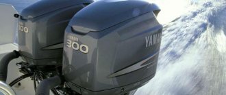
Manufacturers of outboard motors, as a rule, do not make measuring instruments for them. This task is assigned to partner companies. For example, Teleflex Marine produces a large number of tachometers with the Mercury logo. At the same time, it also produces Osculati tachometers and branded Teleflex.
Also, a number of other companies (China, Taiwan) produce a large number of tachometers with Yamaha and Suzuki logos. Therefore, professionals suggest not focusing on the “native” brand of tachometer and, when choosing it, be guided by practical expediency.
Let's look at several of the most popular models of tachometers for outboard motors:
Source
Testing, tachometer adjustment
If the car is equipped with a distributorless or individual ignition system, the tachometer can be connected to any coil. In this case, the readings of the engine rotation speed (rpm) will be inadequate, since an impulse is supplied to the trammel ignition every stroke, while the individual ignition is four times less likely. However, it is possible to calibrate the measuring scale in a new way.
At the first stage of testing, start the engine and check the performance of the system (arrow deflection at idle speed). As a rule, the speed in this mode is in the range of 800 – 1000 rpm.
Next, adjust the reading level. If the tachometer needle deviates slightly, you can connect an additional capacitor with a capacity of about 1 μF between the signal wire and the vehicle ground. On the contrary, if the arrow goes off scale, connect a variable resistance of about 1 kOhm to the open signal circuit and scale the signal.
The next stage is sea trials. With the engine running, the maximum speed is reached. The tachometer needle should not go into the red zone. Otherwise, the adjustment is carried out again. Before starting operation, check the reliability of connections and insulation again. And remember, additional equipment means new problems.