Homemade remote control for boat motor
Simple single-handle remote control
Remote control systems for outboard motors are usually quite complex in design and therefore their manufacture takes a lot of time. Control is carried out, as a rule, by two handles (“gas” and “reverse”), which makes it difficult to control the boat, especially when towing a skier. Options with a single-handle drive, described in articles by L.P. Zimakov in No. 15 and 33 of the collection “Boats and Yachts,” provide for the need for complex alterations in the motor itself.
When developing the proposed version of a homemade remote control for a boat motor, I set out to, on the one hand, simplify the process of controlling the boat as much as possible, and on the other hand, to minimize the necessary modifications in the motor and ensure the possibility of manufacturing the system at home (at the same time with the necessary interlocks that guarantee for example, the impossibility of fully opening the throttle when the reverse is turned off).
The remote control system is made of a single cable, so it was necessary to install return springs to ensure “reset” of the gas and disengagement of the gearbox clutch. The presence of springs greatly simplifies the drive, but, of course, reduces its reliability, and therefore it is necessary to place the “stop” button on the control panel.
Knowing from the experience of many years of using the Whirlwind on a relatively light (120 kg) boat that engaging reverse is required extremely rarely, I refused to move the reverse switch to the control panel. This also simplified the drive design. If necessary, reverse gear is activated directly by the reverse handle on the engine.
Thus, the drive provides forward and neutral engagement and throttle control, all of which are performed with one handle.
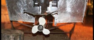
The modification of the motor (in this case, the Whirlwind) is as follows.
To control the carburetor throttle valve, it is necessary to install a 60 mm lever with a cable clamp at the end on the vertical drive shaft.
The cable sheath is secured with a steel or brass clamp to the boss of the motor pan in the existing hole.
A stop made of duralumin or steel 3-4 mm thick is installed on the pallet so that the reverse switch slide rests against it with its front part in the “neutral” position. This stop must be made foldable to enable reverse gear.
The end of the spring is fixed in the hole for fastening the horizontal reverse rod; its second end is attached to the hole in the front part of the pallet. The spring should press the slider against the stop with a force of 3-5 kg and develop a force of 10 kg with the forward travel fully engaged (the rearmost position of the slider).
The Bowden shell is secured in the pan. The cable is pulled through a block located on the back of the pan and attached to the reverse slider using a sheet steel fork and a short pin that fits into the horizontal part of the slider slot.
The preparation of engines of other brands is completely similar, except for switching reverse. On “Neptune”, “Moscow”, “Veterka”, etc., forward gear is activated by moving the lever forward and therefore there is no need for a roller on the cable that changes the direction of movement.
The remote control drive itself is extremely simple in design and manufacture.
Types of steering consoles
These devices come in different sizes and are made using different materials. They also differ in operational parameters. All parts are mounted on a panel to which the motorboat control parts are connected. There are three main types of devices.
Regular steering console
A typical remote control system includes: control cables, steering gear and throttle and reverse controller. Before using the boat, it must be inflated with air and the installation of the necessary attachments must begin.
Typically it includes:
One of the most important and complex parts of a remote control system is the mechanism that converts rotational movements into linear movements of the actuator.
The following gearboxes are used:
For motors with power up to 60 hp. a T-67 gearbox with a steering wheel diameter of no more than 40 cm is installed. For a motor with a power of more than 60 hp. The T-71 gearbox is installed. This gearbox is made of silumin, very durable and wear-resistant.
Note! Console panels are made from plastic, fiberglass, marine plywood, stainless steel and other materials. The kit may include a seat covered with durable fabric, natural or artificial leather. Handrails are made of stainless steel. Such a device weighs 15 - 65 kg.
Mini steering console
From the name it is clear that it has small dimensions: 48 * 51 * 43 cm. It is convenient and easy to install on any compact PVC watercraft. It is quite light: from 2.8 to 4 kg.
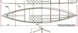
Rice. 1. General view of the remote control
enlarge, 682x1198, 95.6 KB 1 — front cheek;
2 - posterior cheek; 3 - earring; 4 — stop of the reverse shift cable sheath; 5—throttle cable sheath stop; 6—reverse shift cable rod; 7 - bushing; 8 — washer; 5 — spacer sleeve; 10 — reverse switch finger; 11 — handle; 12 — lever; 13 — washer; 14 — throttle finger; 15 — textolite washer; 16 - spring; 17 - throttle cable pull. The open box-shaped body (Fig. 1) consists of two cheeks (1 and 2) with shaped cutouts, connected using bushings with 9 M4 screws. Fingers 10 and 14 are passed through the figured cutouts in the cheeks, at the ends of which the earring 3 is secured with screws on one side and the lever 12 on the other. The throttle cable is attached to the end of finger 14, and the reverse cable is attached to the end of finger 10 using rods 17 and 6. A handle is attached to lever 12, for example from the reverse thrust of the Whirlwind or Neptune motors.
To prevent the throttle cable from moving backward, a friction device is placed on pin 14 between the brushes, consisting of two textolite washers 15 and a spring 16. The stiffness of the spring 16 is selected in such a way that the gas return spring installed on the motor cannot move the drive handle, which is standing in the "full throttle" position. The spring has 12 turns wound with a pitch of 3 mm from OBC wire Ø1.2.
The rotary stops 4 and 5 of the reverse and throttle cable shells are attached to one of the cheeks. Sheath slack adjustment units can be installed at either end, either in the pan or on a stop in the drive.
Rice. 2. Details of homemade remote control
enlarge, 1280x2244, 300 KB 1 — front and rear cheek (dotted line), duralumin δ=4;
2 — earring, duralumin δ=4; 3 — cable sheath stop, steel or brass, 2 pcs.; 4 — cable pull, steel or brass, 2 pcs.; 5 — bushing, brass; 6 — washer, brass; 7 — spacer sleeve, duralumin or brass, 4 pcs.; 8 — reverse switch finger, brass; 9 — gas finger, brass; 10 — lever, duralumin δ=4; 11 — washer, brass, 4 pcs.; 12 — washer, textolite, 2 pcs. The shaped grooves must be made simultaneously in both cheeks. To do this, the cut blanks are fastened with screws passed through Ø4.2 holes in the corners.
It is best to adhere to the following technology when processing grooves. First, drill Ø6 holes in the cheeks with coordinates 30-30 and the lower ends of the lever and earring. Then fasten the shackle and lever to the cheek with an M6 bolt, so that the sides of the lever and shackle are parallel to the short side of the cheek, and drill a hole in all these parts with coordinates 30-70.
Now you need to remove the earring and, using the lever as a jig, drill the two remaining holes in the cheeks. Then, by removing the lever, you can enlarge the holes in the cheeks to Ø8.2 and cut the grooves either with a finger cutter on a milling machine, or by sawing out with a jigsaw after drilling the holes.
Having separated the cheeks, carefully clean the internal surfaces of the grooves, dull the sharp corners and edges. The groove width of 8.2 is not an exact measurement. The groove may be wider; the main thing is that fingers 10 and 14 (Fig. 1) after assembly move along the grooves without jamming.
Rice. 3. Remote control operation diagram
A - axis of the throttle finger;
B - axis of the reverse switching finger. After lubricating all parts with oil, assemble the drive. It works as follows (Fig. 3). In the initial position (the handle is vertically upward), the running engine idles at minimum speed. By tilting the handle towards you all the way, you can increase the speed or, without turning on the reverse, slightly open the carburetor damper to start the engine. When the handle is turned forward, the lever rotates around axis A and moves the reverse slider to the “forward” position. Spontaneous disengagement of the clutch is impossible, since in the extreme position the axis of pin 10 (see Fig. 1) is below axis A, and the slider return spring on the motor “locks” the handle.
Remote control of boat motor
Do-it-yourself installation Long-term continuous operation of a boat using a tiller inevitably causes a feeling of discomfort. The helmsman is forced to remain in an unnatural position for a long time, half-turned. A strong load is transferred to the arms, neck and back, as a result of which the muscles begin to ache. At short distances this is not so pronounced, but making a long journey without breaks for rest seems very difficult. Therefore, the installation of a remote control system on a boat motor should be recognized as an objective necessity. It greatly simplifies the operation of small boats, and is essential for safety on larger vessels.
Manufacturers of some brands of boat motors initially include a remote control in the kit. As a rule, this is a block (commander) that controls the reverse and throttle valve. More advanced systems also allow maneuvering and changing the course of the boat. To do this, they have a steering wheel (also known as a steering wheel). However, motors are often sold without remote control. Then this system must be purchased separately.
Types of remote control
There are two types of systems used to control a ship's engine. They can be used separately or together.
- 1. Systems whose function is to engage forward, reverse or neutral gear, as well as adjust the position of the throttle valve, which allows you to change the propeller speed, affecting the speed of the vessel.
- 2. Systems that are intended for maneuvering, changing the direction of movement of the boat, etc. Their work is based on the same principle as steering in a car.
Construction of gas reverse machines
Remote control of boat motor gas reverse. There are many different design options for gas-reverse machines for remote control of motors. However, based on the presence of some common elements, they can be divided into several types. However, their functionality may differ significantly.
Inside the control unit there is a system of levers with which gears are changed, and the position of the throttle valve and the number of revolutions are changed. This lever system is designed in such a way that the speed is first turned on, after which the lever must be pressed by hand to gradually increase the speed.
Flexible cables or rigid rods are used to connect the commander to the throttle valve and the gear selector. Depending on the type of connection used, the remote control can be either push or pull.
- The first option has become more widespread. Commands from the block are transmitted to the engine using flexible cables.
- In the second case, more rigid elements are used to implement the connection.
Some models of remote control units are equipped with two control systems.
- The first of them sets the boat in motion.
- The second ensures that the engine operates only at idle (in warm-up mode). Engaging the gear lever becomes possible only after the engine temperature rises to a certain level.
In some models, the motor is controlled exclusively by mechanics. However, in more modern modifications, electronics are present at least in a minimal amount. For example, these could be devices designed to lower a motor into the water and lift it, start and stop. There are also additional security features. These include a safety pin in the commander, an ignition system that can only be turned on if you have a key, indicators displaying engine operating parameters and its technical condition.
Any commander with electronic components comes with connecting cables that must be connected to the corresponding motor sockets. When purchasing a system, you should make sure that the connectors on the block and the engine match each other.
Compared to push systems, traction systems are considered more reliable. This is explained by the fact that the rods used in the first type of remote control can be deformed during operation, as a result of which commands are transmitted with some delays. Additionally, placing rigid rods near curved surfaces can be difficult.
Various options for remote control systems can be designed for installation on the starboard or left side of the boat or be universal. The tension of the cables and their length are adjusted using the adjusting screws that are equipped with the unit. The kit also includes special fittings on which remote control cables for the outboard motor are attached.
DIY steering console for a boat
Some owners of inflatable boats resort to making their own steering console. This is due to the fact that factory designs do not fully correspond to the desired comfort during its operation. If you equip the watercraft at the buyer’s request, the price of the product can double.
You can make a similar design yourself if you take into account some points:
The width of the structure should be 45 cm. A battery is installed at its base. The feet of the operator of the watercraft must fit inside the structure. In this regard, all structural elements should not have sharp edges. The main material is waterproof plywood, 12 mm thick.
Manufacturing technology:
The remote motor control includes the following parts:
Source
Boat course control device
Remote steering control of boat motor. In remote control systems designed to change the course of a boat, cables or rods can also be used to communicate between the motor and the steering control unit, consisting of a steering wheel (rudder) and a rack and pinion gearbox connected to it.
When choosing a gearbox for a remote control unit, it is necessary to take into account the power of the motor. This is important because a rotating propeller creates a reaction force that tends to turn the ship around. As a result, maneuvering using muscle power can become almost impossible to control. Due to the gear system installed in the gearbox, the force increases significantly.
In principle, the tiller cables can be directly connected to the steering drum. However, in this case, performance will suffer. In addition, in order to turn the steering wheel, you will have to apply much more force. Nevertheless, such systems (which, unlike gear ones, use not one, but two cables) were quite popular back in Soviet times due to their simplicity of design and lower cost.
Modern remote control models for tiller control, in addition to cables, are also equipped with compensation springs. They are needed in order to increase the comfort of control and eliminate the possibility of an excessively sharp change in the boat's course when turning the helm.
Systems that allow remote control of the motor are simply necessary for owners of large boats, as well as those who often make long trips. It is recommended to purchase them at the same time as the engine and, preferably, of the same brand. As a last resort, you can match the remote control to a previously purchased motor. This will eliminate the possibility of incompatibility between them.
When choosing remote control systems for an outboard motor, you must take into account the characteristics of the engine, as well as the design features of the boat. The optimal remote control seems to be one that allows you to simultaneously control both the speed and the course. Otherwise, the helmsman will have to constantly run from the motor to the control levers and back.
Safe operation of a motorized boat
Before starting to operate a boat with a motor, you must check the compliance of the kit elements. The documentation supplied with the boat indicates what power motor it can be used with. There is no doubt that the higher the engine power, the greater the speed the boat develops, however, installing a 15-20 hp motor on a boat with a length of 250 - 300 cm. the owner is unlikely to sail far. A powerful motor will almost instantly bring the boat into planing mode, the bow of the boat will rise vertically and the boat will capsize. On small boats with an external transom, install a motor with a power of more than 3 - 4 hp. will cause the bottom of the boat to bend, the motor will be pulled under the bottom.
When traveling under a motor, the boatmaster and all passengers must wear life jackets. If the boat suddenly hits a shoal, a large rock or a tree, it may come to a sudden stop. Everyone in the boat can be thrown overboard by the force of inertia. Life jackets will push a person to the surface of the water, raise his head above the water, and prevent him from drowning.
All outboard motors are equipped with an emergency engine stop system. The ignition switch is located on the engine body or on the tiller. To turn on the ignition, insert a pin with a cord into the button. While moving, the cord of the check must be wound around the boatmaster’s hand or fastened to parts of his clothing. Most often, boaters put a lace loop on the flap button of a life jacket pocket or fasten it with a carabiner to a ring sewn to the vest. If the boat hits an obstacle, it stops abruptly, and the driver is thrown from his seat, the pin is pulled out, and the engine stalls. The driver and passengers who fall overboard will not be harmed by the boat propeller.
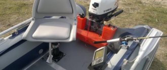
The position of the driver and passengers in the boat and the order in which the cargo is placed are important for safe boat operation. Boat benches (banks) must be held firmly on the ropes, and the chairs must not dangle in the fastenings. There should be an empty space in front of the driver so that during sudden acceleration or braking the load does not fall on him, causing him to become distracted and lose control of the steering. The remote gas tank must be tied to the bottom or walls of the boat, fishing rods, landing nets and spinning rods are installed in mounts along the sides or placed in the bow of the vessel.
Manual boat control
Motors with power up to 50 hp. controlled using a tiller. To move a boat with a tiller control system, do the following:
• having arrived at the reservoir, the boat is inflated, the cans and hard bottom are installed, they are inserted into the oarlocks and the oars are screwed on with nuts;
• the boat is launched into the water, fishing rods, anchors, bags and boxes with fishing and camping equipment are put into it;
• the remote gas tank is tied with straps to the bottom of the boat or attached to a can;
• the motor is installed on the transom of the boat, secured with clamps, and additionally tied to the transom with a safety rope;
• open the air valve on the gas tank. Connect the remote gas tank and the engine with a hose;
• the skipper and passengers board the boat;
Installation of steering console for PVC boat
As a rule, this does not require much effort, but some factors need to be paid attention to. For example:
If a motor with a power of 60-110 hp is used, then a T71 gearbox should be installed. This gearbox does not require additional configuration. In addition, it is made of duralumin and is not afraid of mechanical stress.
The T85 gearbox is designed for steering structures operating in tandem with engines with power up to 160 hp.
Device characteristics:
Boat Remote Control System
Steering a boat using a tiller during long passages is very tiring. The navigator's arms and lower back get tired, and from the stern of the boat it is difficult to observe the situation ahead. To facilitate long water crossings, a remote control system is installed on the bow of the boat.
The remote control system is installed on aluminum and PVC boats, RIBs and plastic boats. It consists of the following parts:
• console or steering column with steering wheel;
• electric engine start system;
• gas reverse and gear shift machine.
Boat motors with a power of 9 hp or more are suitable for connecting the remote control system. The motor is installed on the transom of the boat, the tiller is removed, cables and levers of the remote control system, an electric starter and a battery are installed. The console is installed on the bow of the boat, attached to the side cylinders or to the floor (depending on its design).
As a rule, a boat equipped with a floating system is deflated only for winter storage. All summer the boat sits inflated with the motor installed on the trailer. Having arrived at the reservoir, the motorboat driver drives the trailer into the lake or river and launches the boat into the water.
To control a boat equipped with a remote control system, the boat operator starts the boat with the ignition key, warms up the engine at idle for several minutes, turns on the speed, and starts moving. To turn the boat, the navigator turns the steering wheel, and to change speed and change gears, he moves the throttle reverse lever.
PVC boat steering console
Most PVC boat owners think about how to make boat control convenient and comfortable.
The inflatable boat can be controlled remotely, that is, using the steering console or tiller. When equipping a boat with a steering wheel, you should pay attention to the following factors:
Currently, it is possible to choose a suitable console model, which is due to the availability of a variety of designs from different manufacturers. Despite this, each console is equipped with a steering wheel and a reverse throttle lever, which dramatically reduces the effort required to control the boat.
How to install and connect the steering control to a boat and boat to control an outboard motor
The steering installation method does not depend on which side the cable is laid on! Left side or starboard - it's up to you. Lay it out as you see fit.
Note! Before laying the steering cable, you MUST know the characteristics of the steering gear! Most steering gears allow the cable to be routed along any side, but some only RIGHT or only LEFT.
To select, install and connect the steering to a boat or boat, it is necessary to prepare an outboard motor (BOM) to attach the steering mechanism to it. If the outboard motor was equipped with a “remote control”, then it is ready for installation of a steering remote control. But it often happens that we have a tiller motor and we want to put a distance on it. To do this, we need to do a number of preparatory work.
How to install a steering console on a PVC boat?
You can begin installing the remote system immediately if the engine is included in the kit. If the engine is a tiller engine, it will have to be modified. For this purpose, it is logical to purchase a ready-made kit, but you can also select the necessary parts yourself.
We buy a mounting plate and install it on the engine. We also gain traction. We check whether the engine has a socket for connecting the cable. If not, then we buy a transom cable support. Let's move on to connecting the controls.
This can be done in two ways:
In the first case, the cable jacket is attached to the motor pipe or transom support using a nut. The rod will go through the pipe and come out the other side.
At the end of the steering cable there is an eye to which the rod and motor are connected. The engine, which provides for remote connection, has all the necessary devices, and the tiller engine is being finalized.
In the second case, the cable will have to be routed along the hull of the motorboat and the transom support will have to be mounted on the side of the engine. There is no need for traction. We install the cable adapter. It is necessary so that when the engine turns, the angle of approach of the cable changes, providing some freedom to the power unit.
Installation of the remote control is carried out in the following sequence:
1.Preparing the tiller outboard motor for connecting the steering control.
If the motor is a tiller motor, then in order to connect a remote steering control to it, it must be converted. Most motor manufacturers offer ready-made kits for converting the PLM into a steering remote control. Often, instead of a ready-made kit, the manufacturer allows the owner of the motor to independently determine the need for components. a mounting plate on the outboard motor , to which the steering rod , which must be purchased, will cling. Next, you need to make sure that there is a place for attaching the cable jacket on the motor. As a rule, outboard motors are equipped with a special pipe located in the area of the clamps that attach the motor to the transom. If there is no such pipe on the motor, then a transom support for the steering cable (it comes in a simple version or complete with a transom pad).
Steering remote control connection kit:
— mounting plate in the amount of 1 pc. (if there is no special hole on the motor)
— steering rod in the amount of 1 pc.
— steering rod for two motors in the amount of 1 pc. (if you plan to connect two PLMs or an additional hanger)
— transom steering cable support in the amount of 1 pc. (if there is no special pipe for connecting the cable)
So, everything is ready on the motor side. What's left to do?
Why do you need a steering console for PVC boats?
You can maneuver the PVC boat using a tiller or remote steering. It is attached to the ship and consists of a steering wheel, a stand, a gearbox and a gear selector.
There is a place for installing a stationary echo sounder with GPS, and this ensures the safety of passengers during long journeys, hunting and fishing.
Additional devices are conveniently placed:
Let's celebrate! The device serves as a good counterweight, helping to properly seat people and place cargo. It becomes much more comfortable to sit with a slight rocking motion. Mooring is also somewhat easier - you can approach almost close to the shore if the boat owner is not sitting near the motor.
3. Select, buy and connect the steering control to the boat.
Note! Before purchasing a steering cable, BE SURE to calculate its length, study the classification of steering cables and check the compatibility of the cable with the steering gearbox! Before purchasing a steering gear, study its characteristics - what cable is intended for it, the number of revolutions to fully shift the steering wheel, shaft length, dimensions.
The complete composition of the steering kit for a boat or boat:
— steering cable in the amount of 1 pc.
— steering rod in the amount of 1 pc.
— steering rod for two motors in the amount of 1 pc. (if you plan to connect two PLMs or an additional hanger)
— transom steering cable support in the amount of 1 pc. (if there is no special pipe for connecting the cable)
Sequence of assembly and connection of the steering control.
There is nothing complicated in assembling and connecting the steering remote control, even a schoolboy can handle it: - insert the cable into the steering gearbox ( DO NOT FORGET TO LUBRICATE IT BEFORE! ) - lightly throw the steering wheel onto the gearbox shaft and pull the cable inside the gearbox by turning the steering wheel ( DO NOT Tighten the steering wheel! ) - fasten the cable jacket to the gearbox - install a special plate from the fastening kit for the steering gearbox on the console - remove the steering wheel from the steering gearbox, fasten the gearbox to the plate and lay the cable in the boat - putting the steering wheel on the gearbox, rotate it and ensure that the steering cable rod got out exactly half way ( DO NOT Tighten the steering wheel! ) - check the alignment of the steering wheel (if the steering wheel is in the center, skip the next step)
Steering wheel alignment . There will be a guide soon.
— insert the cable rod into the pipe or transom support and fasten the jacket with a nut — cling to the motor (if a steering rod is used, then adjust its length without moving the steering cable rod from the previously set position) — by rotating the steering wheel left and right, check that the MOTOR ROTATES IN THE REQUIRED SIDE! If when you turn the steering wheel to the left, the motor turns the other way to the right, then the steering cable is not inserted into the gearbox correctly! We take out the cable from the steering gearbox and insert it into the adjacent hole. Then we again check the correct rotation of the motor. - if everything is done correctly, then remove the steering wheel from the gearbox, attach a decorative trim to the console, putting it on the gearbox shaft - put the steering wheel on the gearbox shaft and ONLY AT THE VERY END RELIABLY TIGHTEN THE STEERING WHEEL WITH A NUT!
The steering system has been selected, installed and connected! All that remains is to take a comfortable seat and enjoy the work done!
Examples of completed work.
Removable steering console for PVC boat
Dimensions of the removable device: width – 530 mm, length – 510 mm and height – 510 mm. As a rule, right-sided installation is preferred, although it can also be installed on a left-handed cylinder. The structure weighs about 3 kg and can be installed on an inflatable boat in a matter of minutes.
It is characterized by the following indicators:
The removable structure is attached using special glued adapters and a plastic heel that rests on the floor. It has rounded shapes, which reduces the risk of injury or damage to inflatable parts.